


















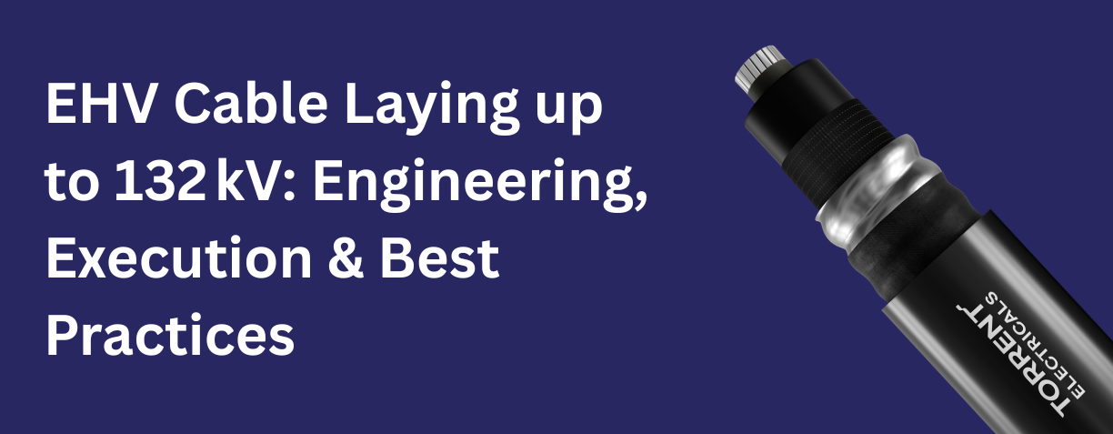
EHV Cable Laying up to 132 kV: Engineering, Execution & Best Practices
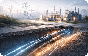
With rapid urbanization and increasing power demand, underground Extra High Voltage (EHV) cable systems have become a preferred solution for reliable and safe power transmission in cities and industrial areas. Cable laying up to 132 kV requires a careful balance of engineering design, precise execution, and adherence to best practices to ensure longterm performance and system reliability.
This blog provides a comprehensive overview of EHV cable laying up to 132 kV, covering engineering considerations, installation methodology, sheath bonding concepts, and industry best practices followed in modern underground power networks.
Understanding EHV Underground Cables up to 132 kV
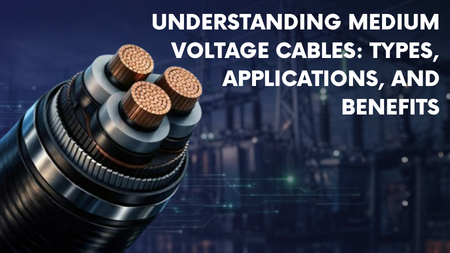
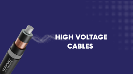
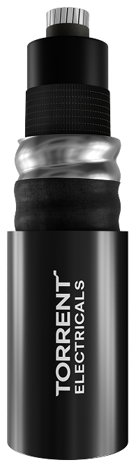
For voltage levels beyond 33 kV, singlecore XLPE insulated cables are predominantly used instead of threecore cables. At 66 kV and 132 kV, singlecore cables offer:
- Better heat dissipation
- Higher currentcarrying capacity
- Flexibility in installation over long distances
- Improved reliability in congested urban corridors
However, the use of singlecore cables also introduces challenges such as induced sheath voltage and circulating currents, which must be addressed through proper bonding design.
Key Engineering Considerations for EHV Cable Laying
Before the execution of EHV cable installation, critical design parameters must be evaluated:
1. Permissible Pulling Tension
To avoid conductor damage during pulling:
- Aluminium conductor: Maximum tension = Conductor area × 4 kg/sq.mm
- Copper conductor: Maximum tension = Conductor area × 7 kg/sq.mm
The selected pulling tension must always remain below the permissible limit.
2. Side Wall Pressure (SWP)
At bends and curves, side wall pressure must be limited to prevent insulation damage: SWP = Pulling tension / Bend radius, typically maintained below 500 kg/m.
3. Minimum Bending Radius
Maintaining the correct bending radius is critical for XLPE cables:
- Nonmetallic sheath: 10D (installation), 15D (positioning)
- Metallic sheath: 15Ds to 22.5Ds (D = cable diameter, Ds = metallic sheath diameter)
4. Duct and Pipe Size at Crossings
At road and trench crossings:
- Inner diameter of pipe ≥ 1.5 × cable diameter
- Adequate clearance ensures smooth pulling and reduces mechanical stress
Handling, Transportation & Storage of EHV Cable Drums
Proper handling of EHV cable drums directly influences cable health:
- Drums must always be transported in upright position
- Laying drums flat is strictly prohibited
- Loading and unloading should be done using cranes or forklifts of adequate capacity
- Drums must be rotated only in the direction indicated by the arrow
- Secure storage with wooden or steel stoppers prevents unwanted movement
These measures protect the cable from mechanical shocks and loosening of winding.
EHV Cable Laying Methodology
1. Route Inspection and Preparation
The entire cable route including trenches, ducts, tunnels, and pits must be thoroughly inspected. Key activities include:
- Cleaning of trenches
- Smooth sand bedding for direct burial
- Removal of sharp objects or debris
- Cleaning and alignment of ducts at crossings
2. Installation Setup
- Cable rollers placed at 2–4 m intervals
- Curve rollers installed at bends to maintain bending radius
- Winch with variable speed control (0–8 m/min) and tension meter
- Proper communication between drum end and winch end
3. Controlled Cable Pulling
- Cable pulling begins slowly under continuous supervision
- Cable grip connected through swivel and shackles
- Drum rotation speed synchronized with pulling speed
- Tension readings monitored throughout the process
Each phase cable is laid individually following the same controlled procedure.
Testing and Dressing of EHV Cables
After completion of laying:
- Outer sheath integrity test is carried out at 10 kV DC for one minute as per IEC standards
- Successful testing confirms sheath health
- Cables are dressed in trefoil or flat formation based on design
- The trench is then ready for backfilling as per approved drawings
Sheath Bonding in EHV Cable Systems
Why Sheath Bonding is Critical
In singlecore EHV cables, electromagnetic fields induce voltage in the metallic sheath. Without proper bonding:
- Dangerous touch voltages may appear
- Circulating currents cause heating
- Cable life and current capacity reduce
As per standards, induced voltage in sheath should not exceed 65 V for systems up to 132 kV.
Cross Bonding – Best Practice for 66 kV & 132 kV Cables
What is Cross Bonding?
Cross bonding is a bonding method where the sheaths of three singlecore cables are transposed and interconnected at defined intervals, typically at onethird and twothirds of the total route length.
Benefits of Cross Bonding
- Nearly zero induced sheath voltage
- Negligible circulating current
- Improved cable ampacity
- Suitable for longdistance underground EHV routes
- No separate earth continuity conductor required
System Components
- Crossbonding link boxes
- Surge Voltage Limiters (SVLs)
- Solid earthing at terminations
Although cross bonding is more complex and costintensive, it is the most reliable and technically superior solution for underground 132 kV cable networks.
Best Practices for EHV Cable Installation up to 132 kV
- Accurate engineering design before execution
- Continuous monitoring of pulling tension during installation
- Strict adherence to bending radius and side wall pressure limits
- Proper bonding and earthing design
- Documentation of test results and installation parameters
- Use of trained personnel and calibrated equipment
Conclusion
EHV cable laying up to 132 kV is a highly specialized activity that demands a strong integration of engineering calculations, disciplined execution, and industry best practices. From safe handling of cable drums to advanced bonding systems like cross bonding, every step plays a vital role in ensuring a reliable, longlasting underground power network.
When executed correctly, underground EHV cable systems provide enhanced safety, improved aesthetics, and uninterrupted power supply—making them an essential part of modern electrical infrastructure.